2.2 Digitization of control circuits Figure 7 Block diagram of the control system of the analog control arc welding inverter power supply The general arc welding inverter power supply is shown in Figure 7. The control loop is an analog system consisting of passive or active components. The welding current, voltage and other parameters are sampled by the sensor LEM block and negatively fed back to the control loop. The feedback amount is compared with the given signal, and is output to the PWM control chip through the PI controller. The PWM signal is electrically amplified and isolated to trigger the on/off of the power switching element to complete the closed loop control of the system. Figure 8 Block diagram of the control system of the single-chip microcomputer controlled arc welding inverter power supply The principle block diagram of the arc welding inverter power supply controlled by single chip microcomputer is shown in Fig. 8. In this system, the MCU mainly completes the given function of the control signal and the overall management of the welder. Although the single-chip microcomputer only completes the signal given in the control system, this has made the arc welding inverter power supply obtain great flexibility in realizing the welding process control, such as CO2 waveform control. For example, the CO2 short-circuit current waveforms of various slopes and different amplitudes can be given by the single-chip microcomputer, so that the process effect of the CO2 welding can be close to the optimum in different current ranges. At the same time, in the arc welding inverter power supply controlled by single chip microcomputer, we noticed that its control core - PI controller and PWM control circuit are composed of analog components, PI controller with operational amplifier as the core, PWM control circuit mostly adopt SG3525 or SG3526. Figure 9 shows the current response curve obtained by different control cycles Through the Matlab simulation study of the arc welding inverter power supply, it shows that for the 80KH arc welding inverter power supply with 20KHz inverter frequency, its maximum control period is 100us. Figure 9 shows the current response curve obtained by Matlab simulation of constant current control of arc welding inverter power supply with different control cycles. The current reference value at the beginning of the simulation is 100A, and the current reference is jumped from 100A to 150A at the time of simulation to 0.01 second. As can be seen from Fig. 9, if the control period is greater than 100 us, the extension of the control period will drastically deteriorate the constant current or constant voltage control effect of the power supply. For a general-purpose single-chip microcomputer, it is impossible to perform analog-digital conversion, PI operation, display, PWM output, etc. within 100us. Therefore, in order to realize the digitization of the PI controller and PWM in the digital control circuit design of the arc welding inverter power supply, it is necessary to re-select the control chip and rethink the overall solution of the control circuit. Based on the Matlab simulation mentioned above, we draw on the design idea of ​​the advanced digital welding machine and propose the digital control solution for the arc welding inverter power supply shown in Figure 10. Figure 10 Block diagram of the control system of digital inverter arc welding power supply In Figure 10, the all-digital welding machine can be divided into two parts: power and control. The power part, three-phase 380V AC power is rectified and capacitively filtered to obtain 540V DC power, through the full-bridge inverter circuit, main transformer and pay-side rectifier bridge, output filter inductor, and finally output the required current and voltage. The control part takes the dual-machine system composed of DSP and single-chip microcomputer as the core, and the current and voltage in the control are sampled and A/D converted, and the feedback value is read by the DSP. The current and voltage reference values ​​are input from the control panel and transmitted to the DSP (ADSP-2181) via the MCU C167CR. The DSP calculates the current and voltage according to the given and feedback amount, and obtains the corresponding IGBT on-time to generate the PWM pulse sequence. Previous page Fluorescent Brightener ER Liquid Optical Brightener ER,Fluorescent Brightener ER-III,Fluorescent Brightener ER-LI,Fluorescent Brightening Agent FORING IMPORT & EXPORT CO.,LTD , http://www.foringfor.cn
The digital signal processing consists of filtering, analog/digital conversion, digital processing, digital/analog conversion, smoothing filtering, etc. of the analog signal, and finally outputs the analog control quantity to complete the digital processing of the analog signal. For the digital processing, at present technology development level, we can roughly choose three types of digital signal processor (DSP), general purpose microprocessor (MPU), and microcontroller (MCU) as processing chips. General-purpose microprocessors (MPUs) are widely used in computers (PCs). Due to their large size, high power consumption, and high price, they are rarely used in industrial control due to their high digital signal processing capability. It is an embedded system application. The most common applications are microcontrollers and digital signal processors. Microcontroller is a so-called single-chip microcomputer in China. It has strong event processing capability, and is rich in interrupts and I/O resources. After more than ten years of development in China, nearly 20 years of development and application, Chinese materials are more, and software and hardware are developed. The conditions are better. However, the data processing capability of the microcontroller is far behind the data signal processor, and it is often incapable of being in a system with real-time and large data processing capacity. The English definition of the digital signal processor is: In brief, DSPs are processors or microcomputers whose hardware, software, and instruction sets are optimized for high-speed numeric processing applications—an essential for processing digital data is analog analog signals in real time. Because the digital signal processor has strong data processing capabilities, it has been widely used in embedded systems, such as mobile phones, sound cards, image capture cards, motor control and so on. In addition, in order to improve the data processing capabilities of general-purpose microprocessors and microcontrollers, DSP has a tendency to merge with the two. For example, the general-purpose microprocessors behind the Pentium MMX incorporate DSP functions to improve network functions, while Siemens' 32-bit TriCore family of microcontrollers integrates the functions of RISC (MPU), MCU and DSP into a single chip core. 
The biggest shortcoming of the analog control system is the limited ability to perform complex processing and the number of components. The parameters of the controller are determined by the parameters of discrete components such as resistors and capacitors. The debugging of the controller is complicated and the flexibility is poor. At the same time, the parameter distribution of the resistors and capacitors affects the consistency of the controller, and the stability of the parameters such as temperature drift affects the stability of the controller. Therefore, it is necessary to carry out research on the digitization of the arc welding inverter power supply. The arc welding inverter power supply controlled by single chip microcomputer is a very important stage in the digital control of arc welding inverter power supply. 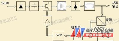
Although the control of the arc welding inverter power source is realized by digitizing in the given part of the signal, it is limited by the processing capability of the single chip microcomputer, and the PI controller and PWM of the power supply still use the analog circuit. Therefore, the digital characteristics are not fully reflected in the welding inverter power supply controlled by the single chip microcomputer. 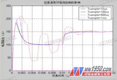
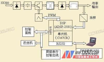
The DSP chip is the ADSP-2181 of ADI. In operation, its control program is loaded by the IDMA port. The loaded program is stored in the program memory and data memory of the chip respectively. The program loading is performed from the high address space to the low address space, and finally completed. 0x0000H is loaded. When the program is loaded, the program is executed sequentially starting from 0x0000H. The loading of the program is controlled by the microcontroller C167CR. Therefore, in the two-machine system composed of C167CR and ADSP-2181, C167CR is the host micro-controller.
The control panel and the wire feeder are controlled by the respective MCUs. The MCU in the control panel is ATMEL's AT29C2051. This is a 20-pin 8-bit MCU with 2Kbytes of Flash on the chip. The digital display and button management of the control panel is completed by two ICM7218As. The wire feeder control uses the MCS80196KC. The main control chip AT29C2051 of the panel, the MCS80196KC of the wire feeder and the C167CR of the main control board communicate with each other through a local serial control bus composed of RS485 interface circuits. The working panel sends the set value of the welding parameters, the welding process type, the jog wire feeding signal, the test gas signal, etc. to the C167CR, while the C167CR reads the current and voltage feedback values ​​of the DSP and the overcurrent and overheat in the welding. Signals such as undervoltage are transmitted to the panel for display. The wire feeder control chip MCS-80C196KC communicates with the C167CR mainly because the C167CR sends commands to the MCS80196KC, such as wire feed speed, wire feed, stop, and so on. There is no direct communication between the wire feeder and the panel. From the perspective of overall management of the welder, the C167CR is the core chip.
In this solution, the single-chip C167CR can establish serial communication with the PC through the RS232 interface. The C167CR serial communication has two functions, one is the network management and control of the welding process, and the other is to carry out the online upgrade of the control program. The essence is to use the C167CR serial loader function to control the program. Online Flash programming.
3. Conclusion
The research and development of digital control technology for arc welding power sources is of great significance. From the point of view of the process effect of the welding machine, the digital welding machine has better process stability and better process effect due to flexible control strategy adjustment, high control precision and good control parameter stability. At the same time, the convenient communication interface function of the digital welding machine provides a good hardware foundation for modern networked production. From the perspective of arc welding process research, digital welding machines provide a new way to implement innovative process control strategies and achieve versatility. The online control program upgrade of the digital welder will play a role, providing a convenient and fast way for the implementation of the new control strategy.
From the perspective of technological development, the timing of digital welding machine research is mature. The first is the development and improvement of digital signal processing theory and computer technology after nearly half a century. It provides a solid theoretical foundation for the application of digital control technology in the field of arc welding and has accumulated valuable experience. Secondly, the components involved in digital control are rich in variety, complete in variety, and easy to obtain. Third, the successful experience of foreign digital welding machines and domestic good reactions prove that digital welding machines have been widely favored. Therefore, the research prospects of digital welding machines are bright, and the future market will certainly be broader.
The international development of welding equipment in the direction of digitalization, the reality of mass marketing of digital welding machines to the Chinese market has proved that in order to have a place in the welding market, we must increase research efforts in this area. Only in the research and production of high-grade welding machines, there is a place for the revitalization and development of the national welding industry.
Optical Brightener OB C.I. 184
Structure: benzoxazole thiophene derivative Purity: 99%min
Appearance: light yellow or milk white powder Melting point: 200-202°C
Volatile conten: 0.5%max Ash content: 0.1%max
Application: Optical Brightener OB can be used for whitening thermoplastic plastics,PVC,PS,PE,PP,ABS,Acetate fier,paint,coating.printing ink,etc..It can be added at any stge in prodess for process for shitening the polymers and can give the finished products a bright bluish white glaze.