| Home>Bearing knowledge>Classification and layout of universal joints |
/*728*90 created on 2018/5/16*/ var cpro_id = "u3440131";
Classification and layout of universal joints
Source: Bearing network time: 2018-07-28
| /*250*250 was created on 2017/12/25*/ var cpro_id = 'u3171089'; |
Classification and layout of universal joints:
1. According to whether the universal joint can change its direction, it can be divided into rigid universal joint and flexible universal joint.
2. Rigid universal joints can be divided into non-equal joints (usually used for cross shaft), quasi-constant joints (such as double joints) and constant velocity joints (such as cages). Three types of universal joints.
(1) The non-constant velocity universal joint cross-shaft rigid universal joint is a non-equal speed universal joint widely used in automobiles; the maximum angle of intersection of two adjacent shafts is 15b-20b. The cross-axis universal joint consists of one Cross shaft; two universal joint forks and four needle bearings, etc. The holes on the two-way joint forks 1 and 3 are sleeved on the two pairs of journals of the cross shaft 2. When the drive shaft changes; The moving shaft can be changed along with it; it can be swayed in the middle direction around the cross shaft; this is accustomed to the need to change the angle and spacing together. Needle bearing 5 is installed between the cross shaft journal and the universal joint fork hole 5 The outer ring of the needle bearing is axially positioned by the snap ring. For the smooth bearing; the grease shaft is usually attached to the cross shaft and the oil passage leads to the journal. The smooth oil can be injected from the grease nozzle to the needle bearing of the cross shaft journal. Where.
Cross-axis universal joint layout: 1- sleeve, 2-cross shaft, 3-drive shaft fork, 4-retainer ring, 5-bearing outer ring, 6-sleeve fork cross-shaft rigid universal joint with simple layout; The strength of the transmission power is high; but in the case where the angle α between the two axes is not zero; the angular velocity transition cannot be transmitted.
When the following two conditions are satisfied; the equiangular speed transmission from the output shaft of the transmission to the input shaft of the transaxle can be completed: the two universal joint forks of the transmission shaft are in the same plane, and the angle between the two axes of the top gimbal is α1 and The angle between the two joints of the second universal joint is α2. Since the drive axle is to be jumped relative to the transmission when traveling; it can not be α1=α2 at any time; in fact, only the transmission to the axle can be approximated, etc. Speed ​​transmission. In the above transmission device; the larger the angle α between the axes; the more uneven the transformation of the transmission shaft; the greater the additional alternating load that occurs; the more helium is used for the life of the machine; the power of the transmission is also reduced; The overall placement should minimize the intersection angle between these axes.
(2) Quasi-constant velocity universal joints Common quasi-constant velocity universal joints have two types of double-type and three-pin type; their working principle is the same as that of double-cross-shaft universal joints to complete constant-speed transmission. .
1- universal joint fork, 2-cross shaft, 3-oil seal, 4-way joint fork; 5-spring spring 6-ball bowl, 7-double fork, 8-ball double joint universal joint It is a double cross-shaft universal joint constant speed transmission that reduces the length of the transmission shaft to a minimum; the double fork is equivalent to the transmission shaft and the universal joint fork on the same plane at both ends. In the output shaft and the input shaft When the angle of intersection is small; the intersection of the two axes of the axis on the arc is very close to the above-mentioned mid-perpendicular line; so that the difference between α1 and α2 is very good. tadpole.
(3) Constant velocity joints The current constant velocity joints commonly used in cars are ball-cage joints; there are also ball-and-clip joints that use the ball-fork joint or the free three-pivot joint. The layout of the star sleeve 7 is connected to the driving shaft 1; the outer surface has six arc-shaped grooves; the inner raceway is formed; the surface of the spherical shell 8 has six corresponding curved grooves; Road.
The six steel balls 6 are placed in the space opposite the raceway of the six sets of tables; and are constrained by the cage 4 in the same plane. The power is transmitted by the drive shaft 1 (and the star sleeve) through the steel ball 6 Output to the spherical shell 8.
Ball cage constant velocity joint 1 - Drive shaft 2,5-steel band, 3-cover 4-cage (ball cage) 6-steel ball 7-star sleeve (inner race) 8-spherical shell ( Outer raceway) The six steel balls in the 9-card global cage constant velocity joint have all the force transmission; the bearing capacity is strong; the torque can be transmitted under the condition that the maximum angle of intersection of the two shafts is 42b; the layout is compact; the disassembly is convenient; Widely used.
In various constant velocity joints; common is the ball cage universal joint; it uses six steel balls to transmit force; the drive shaft and the driven shaft are at any angle of intersection; the steel balls are located at the intersection of the two gardens ; that is, on the bisector of the two-axis intersection; then ensure that the main and driven axes are angularly driven.
Recommend to friends comments close window
| Bearing related knowledge |
Bearing professor teaches you how to view and dispose of the INA bearing fault magnetic pump bearing use and disassembly
The use of FAG bearings and the cause of failure The importance of smooth bearing bearings and the smooth effect of imported bearings Analyze several different ways of car bearings
|
This article links to http://
Please indicate China Bearing Network http://
Previous:The meaning of the suffix of skf paired single-row angular touch ball bearing Next:How to check whether SKF device is proper
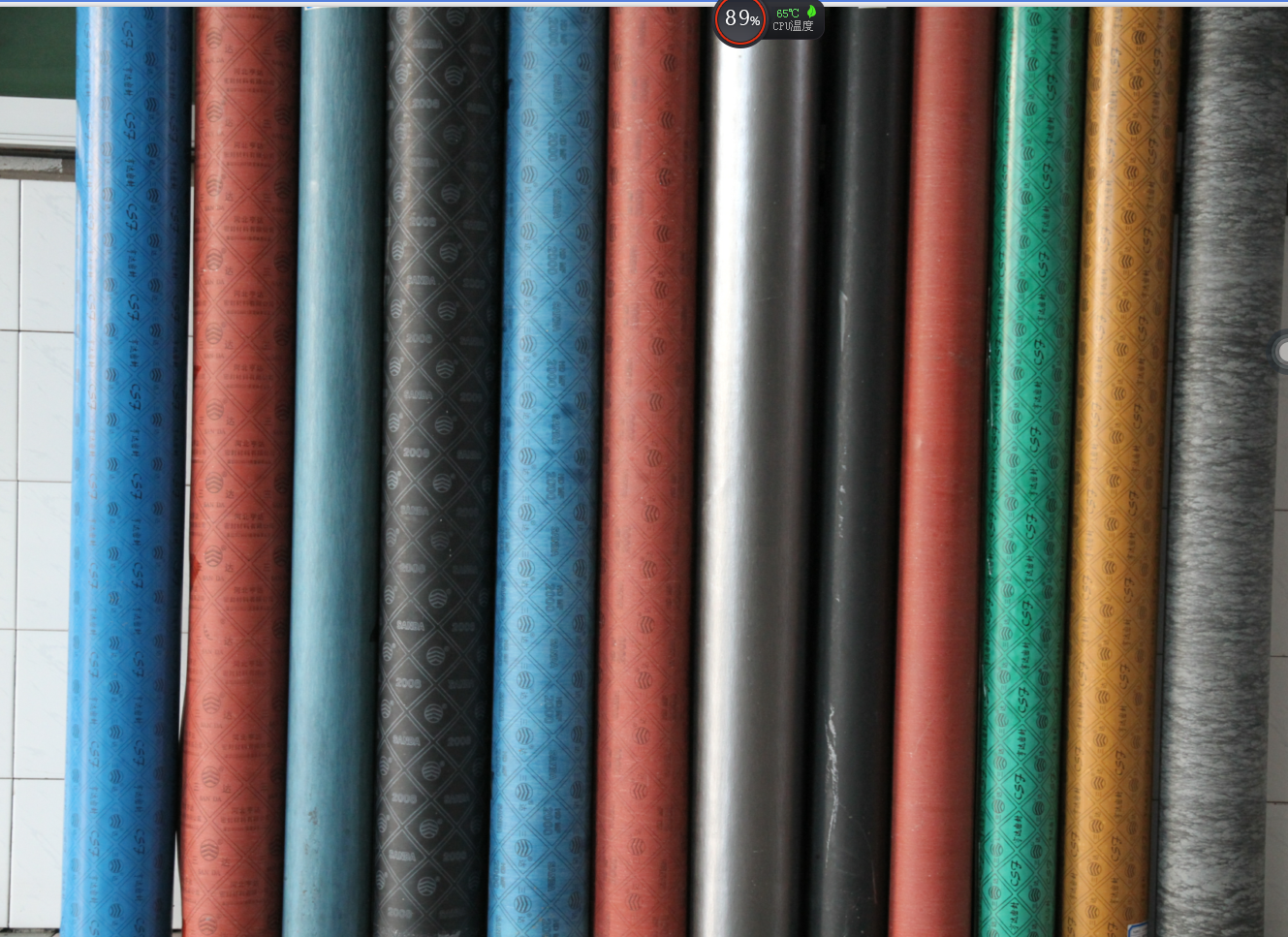
Asbestos Rubber Sheet is made of excellent
asbestos fiber, rubber and other chemical materials.Formed by rolling after
special mixture treatment .The sizes is 0.5~6.0mm can be supplied.It is mainly
for such media as water and vapor and applicable to sealing and heat-insulation
used in the industries as machinery, automobiles, farm, machinery and
petroleum.
Asbestos Rubber Sheet is made
using high-grade raw-material and cutting-edge technologies.For its
multi-purpose in nature, highly flexibility, non-degradable in nature and the
ability to withstand sun, ozone and weather, this range is various industrial
applications.
Model:
1. High Pressure 400-510° C, Pressure:4.0-7.0Mpa
2. Medium Pressure: 300-380° C, Pressure :3.0-4.0Mpa,
3. Low Pressure: 200-250° C. Pressure: 2.0-2.5Mpa
Type:
1. Asbestos Rubber Sheet
2. Asbestos Rubber Sheet With Graphited
3. Asbestos Rubber Sheet With Steel Wire Inserted
4. Wire Reinforced Asbestos Rubber Sheets With Graphied
5. Oil-resistance Asbestos Rubber Sheet
6. Acid-resistance Asbestos Rubber Sheet
7.Corrosion-Resistance
Asbestos Rubber Sheet
DIMENSION:
4100×1500mm; 4500 x 1500mm;2000×1500mm;
1500×1500mm;1500×1000mm;1540x1360mm
1270×1300mm; 3810×1300mm
Thickness: 0.5~6.0mm
STANDARD:GB/T3985-2008
PARAMETER of Asbestos
Rubber Sheet
|
Item
|
XB510
|
XB450
|
XB400
|
XB350
|
XB300
|
XB200
|
|
Lateral Tensile Strength/MPa ≥
|
21.0
|
18.0
|
15.0
|
12.0
|
9.0
|
6.0
|
|
Aging coefficient ≥
|
0.9
|
|
Loss on ignition/% ≤
|
28.0
|
30.0
|
|
Compression ratio/%
|
7~17
|
|
Recovery/% ≥
|
45
|
40
|
35
|
|
Creep relaxation rate/% ≤
|
50
|
|
Density(g/cm3)
|
1.6~2.0
|


Asbestos Rubber Sheet
Asbestos Rubber Sheet,White Rubber Sheet,Black Rubber Sheet,Asbestos Packing Sheet
HEBEI HENGDA SEALING MATERIALS CO.,LTD. , https://www.hengdasealing.com

