Die Casting Camera Housing Parts Die Casting Camera Housing Parts Aluminium Cctv Housing,Die Casting Camera Case,Aluminium Cctv Parts Ningbo Bowang Machinery Co.,Ltd , http://en.zjbwjx.com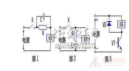
1) Material: Aluminium, zinc;
2) Customers' designs are welcome;
3) OEM/ODM orders are welcome;
4) Die casting machine part of CNC machining precision for Camera Housing Parts;
5) Edges & holes deburred, Surfaces free of scratches;
6) The most advanced test equipments to ensure the quality;
7) Price are strictly based on your design and requested quantity;
8) 100% inspection before delivery.
9) We are focused on cost savings, quality and on time delivery.
Die Casting Camera Housing Parts Processing
Drawing/Model→→2D/3D
Description→→Confirmation of mould design→→Mould stand modeling→→Rough
machining→→Vacuum heat treatment→→Fine machining→→Liner cutting
processing→→
Electric spark discharge→→Mould polish→→Mould assembly
Advantages
Experienced Staff ; Prompt Delivery; Quality Approvals; Good sales service.
We can make all kinds of Die Casting Parts according to customers' design drawings. If you have any requirements
please contact to me directly. I will do my utmost ability to service
for you !
Whether you are currently purchasing overseas or you would like to find a reliable source, we will be your best choice.
Three additional circuit diagrams for relays
[ Huaqiang Security Network News ]
China Security Network Xiaobian gives you a brief introduction to the three additional circuit diagrams of the relay:
1. Relay series RC circuit: The circuit form is shown in Figure 1. This form is mainly used in circuits where the rated operating voltage of the relay is lower than the power supply voltage. When the circuit is closed, the self-inductance of the relay coil will cause the electromotive force to hinder the increase of the current in the coil, thereby prolonging the pull-in time. After the RC circuit is connected in series, the pull-in time can be shortened. The principle is that at the moment when the circuit is closed, the voltage at the voltage across the capacitor C cannot be abruptly changed as a short circuit, so that a power supply voltage higher than the rated working voltage of the relay coil is applied to the coil, thereby accelerating the speed of the current increase in the coil, so that the relay Quickly pull in. After the power supply is stable, the capacitor C does not work, and the resistor R acts as a current limiting.
2. Relay parallel RC circuit: The circuit form is shown in Figure 2. After the circuit is closed, the RC circuit does not work when the current is stable. When the circuit is disconnected, the relay coil generates an induced electromotive force due to self-inductance, and discharges through the RC circuit to make the coil The current decay is slowed down, which extends the relay armature release time and acts as a delay.
3. Relay parallel diode circuit: The circuit form is shown in Figure 3. It is mainly used to protect the driving components such as transistors. When the transistor VT in the figure is turned from off to off, the current flowing through the relay coil will rapidly decrease. At this time, the coil will generate a high self-inductance. The electromotive force is superimposed on the power supply voltage and added between the c and e poles of the VT. The transistor will be broken down, and after the diode is connected in parallel, the self-induced electromotive force of the coil can be clamped to the forward voltage of the diode.