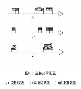
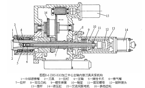
The spindle component is one of the important components of the machine tool, and its accuracy, vibration resistance and thermal deformation have a direct impact on the machining quality. Especially if the CNC machine tool is not manually adjusted during the machining process, these effects will be more serious. The spindle parts of the CNC machine tool should solve the problems of the support of the spindle, the automatic clamping of the tool in the spindle, and the directional stop of the spindle. The support of the CNC machine tool spindle mainly adopts the three main forms shown in Figure 8-5. The front support of the structure shown in Fig. 8-5a adopts a combination of double row short cylindrical roller bearings and bidirectional thrust angular contact ball bearings, and the rear support adopts a pair of radial thrust ball bearings. The high rigidity of this structure can meet the requirements of powerful cutting, and is a form commonly used in various types of CNC machine tools. The front support of the structure shown in Figure 8-5b uses a plurality of high-precision radial thrust ball bearings, and the rear support uses a single radial thrust ball bearing. This configuration has good high-speed performance, but small carrying capacity, suitable for high-speed, light-load and precision CNC machine tools. The structure shown in Figure 8-5c uses a double row tapered roller bearing for the front support and a single row tapered roller bearing for the rear support. This configuration has high radial and axial stiffness and can withstand heavy loads, but this configuration limits the maximum speed and accuracy of the spindle and is therefore only suitable for medium precision, low speed and heavy duty CNC machine spindles. The automatic clamping mechanism of the internal tool of the spindle is a unique mechanism for CNC machine tools, especially machining centers. Figure 8-6 shows the structural components of the spindle of the ZHS-K63 machining center. The tool can be automatically loaded and unloaded on the spindle and automatically clamped. The working principle is as follows: When the tool 2 is installed in the spindle hole, the rear of the tool holder is pulled. The nail 3 is sent to the front end of the spindle pull rod 7, and the cutter is tightened by the elastic claw 5 by the disc spring 9. When a tool change is required, an electrical control command signals the hydraulic system. The piston of the hydraulic cylinder 14 is moved to the left to move the push rod 13 to the left, and the sleeve 10 fixed on the pull rod 7 is pushed to move the entire pull rod 7 to the left. When the elastic claw 5 protrudes a certain distance forward, Under the action of the elastic force, the claw 5 automatically releases the pull stud 3, and at this time, the pull rod 7 continues to move to the left, the end of the air nozzle 6 loosens the top of the cutter, and the robot can take out the cutter for tool change. Before the knife is loaded, the compressed air is ejected from the air nozzle 6 to blow off the dirt in the cone. After the robot loads the cutter, the pressure oil passes through the left chamber of the hydraulic cylinder 14, so that the push rod is returned to the original position. Under the action of the spring, the tool is tightened by the tie rod 7. The coolant nozzle 1 is used to cool the tool at a large flow rate during cutting. Ce Concrete Mixer,Portable Concrete Mixer,Ready Concrete Mixer for Sale Hengxing Industry Machinery Co., Ltd. , http://www.fjconcreteplant.com